Ī¶Technical parameter Ī÷Electric
parameter a. Conforms to standards: .2
b. Rated voltage (Ue): 230/400V; 50/60Hz c.
Rated breaking capacity Icn: 6kA d. DC short
circuit breaking capacity: maximum 60V/1 pole
25kA e. Rated current In: 50, 63, 80, 100,
125A e. Trip characteristic: C, D
characteristic curve f. Maximum connecting
fuse: 200A gL (>20kA) g. Selectivity level:
3 h. Working ambient temperature:
-5Īµ~+40Īµ i. Case protection level: (after
installation) j. Life: more than 8000 times of
on-off operation
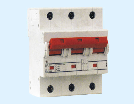
Ī÷Machinery parameter a. Exposed face
length: 45mm b. Case height: 90mm
c. Case width: 27mm each pole (1
pole) d. Installation mode: use IEC standard
guide 35mm e. Terminal mode: lifting
connecting terminal f. Terminal
connecting capacity: 2.5-50mm2
Ī÷Main characteristic a. High breaking
capacity and current limiting characteristic
b. Contactor mode indicator c. Special
accessory series Ī¶Outline size
Used in commerce and
civil circuit for short circuit and over load protection.
Rated current In (A)
Rated breaking capacity Lcn
(kA)
1.5 modulus
3 modulus
C characteristic
curve Ī÷Transient behavior 5~10In Ī÷Mainly used for
commerce and civil building distribution protection.
20
25
M-LH-100/20/1/C
M-LH-100/20/2/C
25
25
M-LH-100/25/1/C
M-LH-100/25/2/C
32
25
M-LH-100/32/1/C
M-LH-100/32/2/C
40
25
M-LH-100/40/1/C
M-LH-100/40/2/C
50
25
M-LH-100/50/1/C
M-LH-100/50/2/C
63
25
M-LH-100/63/1/C
M-LH-100/63/2/C
80
20
M-LH-100/80/1/C
M-LH-100/80/2/C
100
20
M-LH-100/100/1/C
M-LH-100/100/2/C
125
15
M-LH-100/125/1/C
M-LH-100/125/2/C
D characteristic
curve Ī÷Transient behavior 5~10In Ī÷Mainly used in
industry power distribution field.
Used in commerce and
civil circuit for short circuit and over load protection.
Rated current In (A)
Rated breaking capacity Lcn
(kA)
4.5 modulus 3
pole
6 modulus 4
pole
C characteristic
curve Ī÷Transient behavior 5~10In Ī÷Mainly used for
commerce and civil building distribution
protection.
20
25
M-LH-100/20/3/C
M-LH-100/20/4/C
25
25
M-LH-100/25/3/C
M-LH-100/25/4/C
32
25
M-LH-100/32/3/C
M-LH-100/32/4/C
40
25
M-LH-100/40/3/C
M-LH-100/40/4/C
50
25
M-LH-100/50/3/C
M-LH-100/50/4/C
63
25
M-LH-100/63/3/C
M-LH-100/63/4/C
80
20
M-LH-100/80/3/C
M-LH-100/80/4/C
100
20
M-LH-100/100/3/C
M-LH-100/100/4/C
125
15
M-LH-100/125/3/C
M-LH-100/125/4/C
D characteristic
curve Ī÷Transient behavior 5~10In Ī÷Mainly used in
industry power distribution field.
50
25
M-LH-100/50/3/D
M-LH-100/50/4/D
63
25
M-LH-100/63/3/D
M-LH-100/63/4/D
80
20
M-LH-100/80/3/D
M-LH-100/80/4/D
100
15
M-LH-100/100/3/D
M-LH-100/100/4/D
Ī¶ Energy
consumption Conforms to standards of Ī÷M-LH (20-100) and fuse D0 or NH short circuit breaking
capacity Ī÷ 1.4 high selectivity can be more than 1.4kA: Ī§no
selectivity function Fuse wire D01, D02, D03
selectivity
M-LH rated current
Fuse wire gL rated current (A)
25
35
50
63
80
100
C characteristic curve
20
<0.5
1.0
2.0
2.9
3.9
7.6
25
1.0
1.9
2.8
38
7.6
32
1.0
1.8
2.7
3.6
7.0
40
1.6
2.2
3.0
5.6
50
2.1
2.8
5.2
63
2.7
4.8
80
4.3
100
125
D
characteristic curve
20
<0.5
0.9
1.7
2.5
3.4
6.7
25
0.9
1.6
2.3
3.2
6.2
32
0.9
1.5
2.3
3.0
6.0
40
1.4
2.0
2.6
4.7
50
1.8
2.3
4.3
63
2.1
3.7
80
3.1
100
Fuse wire NH-00
selectivity
M-LH rated current
Fuse wire gL rated current (A)
25
35
40
50
63
80
100
125
160
200
C characteristic curve
20
<0.5
1.0
1.3
1.9
2.7
3.7
6.7
17.0
25.0
25.0
25
0.9
1.3
1.8
2.6
3.5
6.5
17.0
25.0
25.0
32
0.9
1.2
1.7
2.4
3.3
6.0
15.0
23.0
25.0
40
1.4
2.1
2.9
4.8
12.0
18.0
25.0
50
1.9
2.7
4.5
11.0
17.0
25.0
63
4.2
10.0
15.0
25.0
80
3.8
8.5
12.0
25.0
100
7.0
10.0
25.0
125
25.0
D
characteristic curve
20
<0.5
0.8
1.1
1.5
2.3
3.1
5.6
16.0
25.0
25.0
25
0.7
1.0
1.4
2.1
3.0
5.3
14.0
23.0
25.0
32
0.7
1.0
1.3
2.1
2.9
5.0
13.0
22.0
25.0
40
1.1
1.8
2.5
4.2
10.0
15.0
25.0
50
1.6
2.36
3.8
8.5
13.0
22.0
63
2.1
3.2
7.0
10.5
18.0
80
2.8
5.5
804
15.0
100
4.8
7.5
12.5
Ī÷Trip characteristic conforms to standards of
() Ī÷B characteristic curve: used in lighting
distribution systems Ī÷C characteristic curve: used in lighting
distribution, socket circuit or some power
distribution systems Ī÷D characteristic curve: used in power or
other high inductive load circuit.